

How To Repair Air Gaps In Sip Panels In Existing House
Introduction
Inside This Page
- Introduction
- Description
- Lessons Learned
- Emerging Issues
- Relevant Codes and Standards
- Additional Resources
Today's architects are faced with the urgent task of achieving energy-efficient and high-performance building enclosures. Structural Insulated Panels are an option for part of the enclosure assembly that tin help achieve these goals. SIPs practice an impressive job of slowing down the transfer of heat, air, and vapor through the assembly. They also dramatically reduce the drying potential of the enclosure, lessening its ability to recover from inadvertent water intrusion. Such an airtight assembly with slap-up thermal resistance tin result in a loftier-operation and durable enclosure if detailed and congenital correctly, or information technology can result in the rapid rot and disuse of a building's chief structure if detailed or built incorrectly. Reference Edifice Science Corporation's Building Science Insight BSI-028: Energy Flow Beyond Enclosures.
History
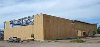
Figure ane: Example of SIPs used as infill with a structural steel frame, Silvis Schoolhouse, Illinois.
Photograph Credit: Steven Schaefer Assembly, Inc. Consulting Structural Engineers
The Forest Products Laboratory in Madison, Wisconsin introduced the idea of what is now known equally Structural Insulated Panels (SIPs) in 1935. The Laboratory's prototype panels consisted of framing members, plywood and hardboard sheathing, and insulation. These initial panels were used to build exam homes that were disassembled and tested after thirty years to reveal that the panels retained their initial force values. Frank Lloyd Wright used a form of structural insulated panels in the Usonian homes built in the 1930's and 1940'southward. In 1952, Alden B. Dow created the first foam core SIPs which were being mass-produced by the 1960's. (Morley)
Today, SIPs are prefabricated building components for employ as walls, floors, roofs, and foundations. SIPs provide a continuous air and vapor bulwark too as increased R-value when compared to traditional construction. Construction costs associated with SIPs are comparable to more conventional edifice methods when savings associated with labor costs, material waste matter, and energy efficiency are considered. (Morley)
Description
Structural insulated panels are equanimous of an insulated foam core between two rigid lath sheathing materials. The foam cadre is generally one of the post-obit: expanded polystyrene (EPS), extruded polystyrene (XPS), and polyurethane foam (PUR). With EPS and XPS foam, the assembly is pressure laminated together. With PUR and PIR, the liquid foam is injected and cured under loftier pressure level.
The nearly common sheathing boards are oriented strand boards (OSB). Other sheathing materials include: sheet metal, plywood, fiber-cement siding, magnesium-oxide board, fiberglass mat gypsum sheathing, and blended structural siding panels.
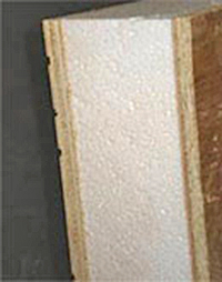
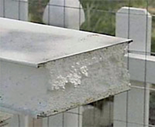
Figure 2: Typical SIP with OSB and EPS.
Source: www. housing.com
Figure three: Sheet Metallic SIP.
Source: www. steelsipconstruction.com
Each sheathing material and foam type has its benefits and drawbacks. The type of SIPs selected depends upon the building type and site weather condition. The following tables outline the benefits and drawbacks of the virtually common sheathing and cream types.
Tabular array one: Capsule Type Chart
| Capsule Type | Benefits | Drawbacks |
|---|---|---|
| Oriented Strand Board (OSB) | Load bearing; readily available; tested; large panel size up to eight' x 24' | Subject to mold and a reduction in structural capacity if exposed to moisture; non burn down resistant; must be treated for termites; hard substrate for nigh common joint tapes |
| Sheet Metal | Reistant to mold; can be load-bearing; very light; unlimited lengths when made from coil stock | Must be galvanized or stainless steel; not load begetting |
| Plywood | Lateral forcefulness | Availability; cost; express panel size; subject field to mold and reduced structural chapters if exposed to wet for a prolonged period of time; not fire resistant; must be treated for termites |
| Fiber Cement Siding | Resistant to mold, termites, and fire | Availability; weight; testing; limited console size |
| Magnesium Board | Resistant to mold, termites, and fire | Availability; testing; express panel size |
| Fiberglass Mat Gypsum Sheathing | Resistant to termites and fire | Not structural; limited panel size |
| Blended Structural Siding Panels | Resistant to mold and termites; pre-primed materials bachelor | Not fire resistant |
Table 2: Core Blazon Nautical chart
| Foam Core | Benefits | Drawbacks |
|---|---|---|
| Expanded Polystyrene (EPS) | Least expensive; thickness options are only limited past the cream manufacturer; availability; fastest to modify in field; most benign blowing agent | Produced with HBCD* |
| Extruded Polystyrene (XPS) | Strength; water resistant | Availability; produced with HBCD* |
| Polyurethane Foam (PUR) | Highest R-value/inch; forcefulness, h2o resistant | Nearly expensive; harder to modify thickness limitations; creep; availability; produced with chlorinated phosphate flame retardants** |
*HBCD: hexabromocyclododecane - a brominated burn down retardant classified past the Eu (REACH program) as persistant, bioaccumulative, and toxic (PBT).
**Not every bit chancy as near brominated flame retardants, only health and environmental concerns even so exist.
Source: BuildingGreen Insulation Study
Table 3: Foam Technical Data
| Foam Blazon* | EPS Foam | XPS Foam | PUR Cream |
|---|---|---|---|
| Density in Panel (lb/ft3) | 0.ninety | 1.5 | two.three – 2.5 |
| Compressive Strength @ 10% deformation (psi) | ten | 20 | 35 |
| R-value/in @ 75° F | iii.half-dozen | 5.0 | half-dozen.54 |
| Permeance per inch | 5 | 1.1 | 2.00 |
| Common Fire Retardant | HBCD | HBCD | TCPP |
| Mutual Fire Rating Grade | 1 | 1 | 1 |
| Common Bravado Agent | Pentane | HFC—134a | HFC—245fa |
* Near SIP manufacturers use a 0.95 minimum density.
Fundamentals
Structural Design and Structure
SIPs behave similarly to a broad flange steel cavalcade in that the foam cadre acts as the spider web and the sheathing responds as the flanges. Under axial loads, the sheathing responds similarly to a slender column, and the foam core acts equally continuous bracing preventing the panels from buckling. But as wide flange sections increase in strength with increased depth, thicker cores result in stronger panels in pinch and bending. (Morley)
SIPs are designed to resist not only centric loads, but also shear loads and out of plane flexural loads. The panels' power to resist bi-axial bending and lateral shear allow them to exist used equally roofs and floors. SIPs panels are acceptable to apply as shear walls in all seismic design categories. A structural engineer should determine if a secondary structural system is required based on the design loads.
To date, the tallest structure constructed exclusively of SIPs is four stories. Taller structures are possible; however, design limitations are due to the fact that SIPs are bearing walls and therefore open up spaces at lower floors are more than difficult to achieve. Oft large SIPs structures rely on a secondary framing organization of steel or timber to satisfy requirements for unobstructed spaces. Unique screw connections are bachelor to attach SIPs to wood, calorie-free gage steel, and structural steel up to 1/4 inch thick.
It is imperative for foundations for SIPs panels to be level. In that location is little tolerance for differential settlement. If there is substructure shift, it will compromise the sealant of the panels' joints which may cause moisture infiltration. Commanded deflection tolerances set by the manufacture of the panels and sealants should be consulted when designing the foundation. Small-scale imperfections may be accommodated with careful, skilled installation.
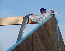
Figure iv: SIP ridge and gable end tape/gasket seal. Photo Credit: SIPschool
Joint design is imperative for structural and long-term durable functioning. One particular weakness of SIPs panels is air penetration from the interior at joints or penetrations. In cold climates, if warm humid interior air reaches the interior face of the outer capsule layer information technology tin condense, causing rot and deterioration. Frequently this outer layer is OSB, which is particularly susceptible to moisture impairment.
Proper joint design should be given special attending, and if properly executed in the field, will eliminate the air infiltration problems. The primary joint design generally includes seals within the thickness of the console, typically spray foam or gaskets. There should be an overflow seeping of the spray foam at the joints to point a full depth joint seal as shown in the figures below. An additional secondary seal air seal of tape or gasket should be provided at the interior face up of the console, especially in cold climates.
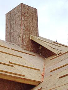
Effigy five: Instance of SIPs used for roof panels showing seeping of sealant at SIP joint, Breckenridge, CO.
Photo Credit: CW Associates, PLLC, (CWA Compages)
Figure 6: Example of SIPs used for wall and roof panels showing seeping of sealant at SIP joints, Winter Park, CO.
Photo Credit: CW Associates, PLLC, (CWA Compages)
Two of the nearly widely used panel articulation connections are the surface spline and the block spline. The surface spline joint connection consists of strips of OSB or plywood inserted in slots in the foam just inside each peel of the SIP. The cake spline is a sparse and narrow SIP assembly that is inserted into recesses in the foam along the console edges. The surface spline connection and the block spline connection result in a continuous foam core beyond the panels, eliminating air infiltration at the joints. If structurally required, panel joints can be reinforced with one or more than 2x lumber studs or Laminated Veneer Lumber (LVL) along the edges of the two panels to be continued. One disadvantage of this type of connectedness is that a thermal bridge is created at the joint. Some other articulation connexion, mechanical Cam locks, create a tighter articulation betwixt panels, only make upward merely a minor percentage of the market. In improver, Cam locks can just be set in PUR because the locks crave a higher tensile strength than provided by other foams and the foam needs to expand and set around the lock's flanges. In any type of connection, the seam forth the sheathing must be covered with a continuous line of foam sealant and/or panel tape.
Effigy seven: Block Spline
Figure 8: Surface Spline
Effigy 9: Cam Lock
Openings can occur anywhere within the console, including at the edges and corners. The panel cream can be recessed to accept 2x lumber headers. However, panels tin be reinforced at headers so that additional structure is non required during structure. The within panel and foam can be subtracted to provide beam pockets for roof and flooring joists. Any opening within the SIPs that accepts another enclosure element must be properly sealed.
Plumbing chases are usually located in furred out framing or conventional framing should be used for plumbing walls.
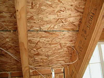
Electrical chases 1-inch to 1-1/2 inches in bore can be incorporated into the SIPs during the manufacturing phase. Foam is practical in whatever gaps resulting after the installation of electrical wiring.
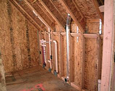
Effigy 10: Instance of SIPs used for wall and roof panels and a furred out wall at exterior panel for vents and plumbing, Tabernash, CO.
Photograph Credit: CW Associates, PLLC, (CWA Compages)
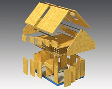
Figure 11: Exploded Axonometric of a SIPs Edifice.
Source: www.lord's day-spaces.com
Other unexpected penetrations made in the panels during construction should be made 1-inch larger in diameter than the penetrating pipe to allow for the awarding of foam sealant.
Typical wall panel thicknesses are four-1/2 inches and 6-i/2 inches. The largest panel size to appointment is ix' x 24'. Curved panels are possible although not mutual and it is frequently more practical to use stud framing for not-orthogonal geometries.
Roof panels are typically 10-1/four inches and 12-one/4 inches thick. Roof panel thickness depends upon the required R-value and span. EPS and XPS panels can be fabricated upward to 12-i/4 inches thick. PUR and PIR panels tin exist fabricated up to 8-ane/4 inches thick. Stop wall panels for diverse roof profiles can be accomplished with SIPs.
Operation Issues
Thermal Performance: The quality of a edifice's envelope is measured by its ability to preclude infiltration of exterior air. Recent energy code standards require an air tight edifice envelope, and a SIPs building with properly sealed console joints is inherently airtight. The results of blower door tests on a room with SIPs walls and ceilings, one window, 1 door, and pre-routed wiring chases and electrical outlets compared to a identical room of 2x6 studs, OSB sheathing, fiberglass insulation, and drywall showed the SIPs structure to leak 90 percent less than the stud structure. (SIPA, ORNL)
The Whole Wall R-Value of a wall assembly is currently the most accurate method of quantifying its thermal performance. The Whole Wall R-Value takes into account the resistance of heat flow through an opaque cantankerous exclusive area of the insulation and structure while bookkeeping for the loss of energy at the interfaces of the wall with the roof and flooring and at corners and fenestrations. The Whole Wall R-value of a 4-inch SIP wall is xiv. The Whole Wall R-value of a 2x4 wall is less than 10. The Whole Wall R-value of a 2x6 wall is betwixt 11 and xiii.7 depending on the quality of the installation of batt insulation. The elimination of thermal bridging and a more air tight envelope contribute to the higher Whole Wall R-Value of SIPs walls when compared to conventional metal and wood stud walls. (SIPA, ORNL)
Tabular array 4: Typical SIP Whole Wall R-values
| Thickness | EPS | XPS | PUR |
|---|---|---|---|
| Density in Console (lb/ft3) | 0.ninety | 1.5 | 2.three-2.v |
| 4-ane/2" | thirteen.1 | 17.7 | 22.7 |
| 6-i/2" | 19.nine | 27.2 | 35.1 |
| 8-1/4" | 26.0 | 35.5 | 46.0 |
| 10-1/4" | 32.9 | 45.0 | NA |
| 12-1/4" | 39.8 | 54.half dozen | NA |
Table 4 Notes:
- Based on 8-ft wall with single bottom plate double top plate and single 2X band around rough openings.
- Based on Spline, Cake Spline, or Cam lock panel articulation connections.
- Values are for the panels only and practice not include contribution from terminate materials.
- Values volition vary depending on wall height and number of crude openings.
- In roof applications, the utilise of forest splines will reduce these values.
Wet Protection: Since the SIPs' foam core acts as a vapor barrier, the conditions barrier must be permeable in gild to allow the SIPs sheathing panels to dry out outward. A continuous air space, between the drainage plane and the exterior cladding, and vented openings at the top and bottom of the walls to let for convective air flow is recommended to ensure adequate drying of the SIPs. This too applies to SIPs used as roof structure. Air should exist able to flow under the roofing fabric between the eave and the ridge. In addition, all panel joints, openings around windows and doors, and other chases should be properly sealed and/or flashed to prevent moisture infiltration.
Particular attention to details that ensure that interior air infiltration never reaches the outer sheathing layer is imperative.
For areas field of study to flooding, waterproof sheathing materials such as cementitious skins or thermoplastic skins are an ideal culling to OSB. (Uddin) However, if SIPs with OSB sheathing come up into contact with water, the structural integrity of the panels can exist saved if the OSB is quickly exposed to allow to dry.
Burn Condom: Since the majority of SIPs structure is for Blazon V construction where the SIP walls are load begetting, NFPA 285 compliance does not utilize. At this time, there appears to be no NFPA 285 tests that have been performed for SIPs wall construction. Refer to a Building Envelope Consultant if you plan to use SIPs construction where the NFPA 285 test may be required.
Acoustics: SIPs insulate against loftier frequency noise better than low frequency noise. SIPs are non recommended to use as floors over an open interior space without the application of a sound barrier.
Material/Finish Durability: The fastener requirements for outside cladding and interior finishes are specific to the console manufacturer; consult the manufacturer's specifications for this information. It is recommended that a ventilation space is created with furring strips between the exterior face of the panel and the exterior cladding. This allows for the panels to dry out when water vapor enters the panel.
Maintainability: The quality of SIPs is set in the manufacturing phase. Proper lamination and smooth surfaces and edges volition ensure that the SIPs can suffer long-term use as long as the structural skins are properly protected from degradation. It is of import to note that if moisture causes deterioration of the skins, then there is a structural issue that must be repaired. Repairs can require replacement of a much larger expanse than the just the deteriorated portion.
Cream insulation is subject field to insect and rodent infestation. Insecticides are added to the panels during manufacturing or later on site.
Full general Detail Principles
- The SIP outside design building envelope form is just limited to the design imagination. (See Figures 1, 12 & 13)
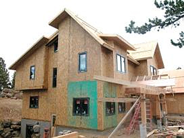
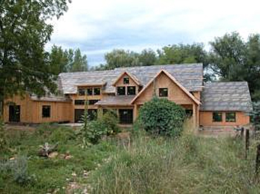
Figure 12: Instance of SIPs used for wall and roof panels in a complicated architectural form, Nederland, CO.
Photograph Credit: CW Associates, PLLC (CWA Architecture)
Figure 13: Instance of SIPs used for wall and roof panels in a complicated architectural form, Boulder, CO.
Photo Credit: CW Assembly, PLLC, (CWA Architecture)
- SIPs can accept any blazon of properly designed exterior cladding.
- SIP console joints, voids, and penetrations to be provided with an airtight seal by continuous foam sealant, gaskets, and SIP tapes. Continuity of the inner air seal is imperative to long-term functioning.
- Verify SIP span and structural limit requirements. (See Figures 1, 14, 16, & 17)
- Verify SIP blast, spiral, and Cams - attachment patterns, fasteners types, and spacing requirements. (See Figures 14, 15, 16, & 17)
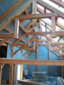
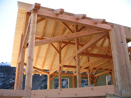
Figure xiv: Instance of SIPs used for wall and roof panels with drywall on a timber frame structure, Breckenridge, CO.
Photo Credit: CW Associates, PLLC (CWA Architecture)
Effigy 15: Example of SIPs used for wall panels with drywall and roof panels with natural language and groove (T&Yard) decking, Lake Alcova, WY.
Photograph Credit: CW Associates, PLLC, (CWA Architecture)
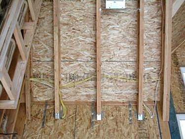
Figure sixteen: Example of SIPs used for wall and roof panels in a dormer with truss joist framing, Boulder, CO.
Photo Credit: CW Assembly, PLLC, (CWA Architecture)
Effigy 17: Instance of SIPs used for wall and roof panels showing microlam and truss joist hanger connections and strapping, along with wiring, Glacier Park, CO.
Photograph Credit: CW Associates, PLLC, (CWA Architecture)
- Provide exterior roof and wall ventilation/drainage plane systems.
- Don't provide plumbing in the exterior SIP walls. (Come across Effigy 10)
- Coordinate any in SIP electric.
- Properly sealed SIPs will provide for the air, vapor, and thermal barriers.
- Detail for a continuous inner line of redundant air seal at all joints and penetrations using sealant, foams, tapes, and gaskets. (See Figures 4, five, & 6)
- Provide for the outside wall and roof (WRB) water resistance barriers. Note that the WRB should be vapor permeable and must make all joints h2o and airtight.
- Provide advisable flashing systems at all exterior building envelope openings and penetrations.
- Properly designed HVAC systems are required to address the air tightness and energy efficiency inherent with SIP designed buildings.
General Associates Principles
- Foundation and/or floor deck to exist square and level within tight tolerances for effective SIP installation.
- Item store drawings shall exist provided by the manufacturer for coordination and to address the General Item Principles as mentioned higher up.
- SIP panel skins need to have solid full bearing support. Review the installation of the SIP bearing plates for this support.
- The projection design team should review any field cutting of SIPs.
- Foam sealing of SIP panel joints shall be reviewed for continuous full deep sealing. Normally proper foam sealant installation can be observed past foam seeping at the joints that will need to be cleaned off the panel outside surface. (See Figures v, 6)
- The inner redundant air seal is commonly accomplished with gaskets placed over the begetting points, spray foam, and with tapes at exposed joints. Carefully select tapes and primers suitable for panel type for long-term adhesion to the panels. Note that OSB is specially problematic for most common construction tapes. (Run across Figures 4, five, & half-dozen)
Lessons Learned
The Juneau, Alaska Roof Reports that accept been published (see publications list beneath) described prove that interior air infiltration idea the joints in the SIP roof panels indicated premature deterioration of the superlative of the OSB peel of the roof panel joints. The general conclusion the building science squad reported was that the moisture damage was due to show of the lack of proper joint panel sealing.
Logistical and Construction Assistants Problems
Service Life: The service life expectancy of components that are mated with the SIP assembly should match the service life expectancy of the SIP wall itself. Components include durable flashing materials, structural components in the SIP console, sealants, cream, tape, gaskets, fasteners, etc.
Field Mock-up: A mock-up representative of the design assembly should be required for all SIP walls. This is all-time completed as a small called area of the construction prior to total construction production, so that at that place is an opportunity to make blueprint changes based on the observation of the field mock-upward.
Field Observation of SIP Walls: Require field observation for the installation of the SIP walls, and its components, for quality balls of SIP wall fabrication and installation.
Store Drawing Coordination: Crave SIP wall installation shop drawings showing all adjacent construction and related work, including flashings, gaskets, sealants, structural components in the SIP's, attachments, and bespeak sequencing of the work.
SIP wall systems require expertise on the role of the edifice designer, the manufacturer, the fabricator, and the installer. The Architect and Engineer of tape may consider engaging an outside consultant, if such expertise is not available within the project team.
Other Considerations
Although the total time for manufacturing and assembling a SIPs structure is less than that of a framed construction, more than time is required in planning. Openings in the panels, non-orthogonal designs, electrical, and AV coordination must be determined prior to the manufacturing of the SIPs.
Window installation is similar to that of wood frame construction. The manufacturer's specifications should be consulted to insure proper installation.
SIPs manufactured in the United States no longer use adhesives with urea-formaldehyde in OSB panels. The foam cores consist of 98-pct air and are fabricated using non-CFC bravado agents.
A properly congenital SIPs structure volition be airtight; therefore fresh-air ventilation is required of the mechanical system to forbid interior moisture problems and the build-up of indoor air pollutants.
The contractor and the installers should be experienced with SIPs and it is recommended they have become registered through SIPA and/or SIPschool or be trained by the Brotherhood of Union Carpenters to help forbid poor installation of SIPs by a coiffure that is not familiar with the product. The Architect and Engineer of tape along with the SIP manufacturer should notice the structure of the SIPs for compliance with the canonical project submittals.
Details
The details associated with this section of the BEDG on the WBDG were developed by committee and are intended solely as a means to illustrate full general design and construction concepts only. Appropriate apply and application of the concepts illustrated in these details will vary based on functioning considerations and environmental conditions unique to each project and, therefore, practise non stand for the final opinion or recommendation of the author of each section or the commission members responsible for the evolution of the WBDG.
The details, graphics, and related data shown in the details are intended to illustrate basic design concepts and principles only and should be considered collectively with the advisable narrative sections of the Whole Edifice pattern Guide (WBDG). The information contained therein is not intended for actual construction, and is subject to revision based on changes and or refinements in local, land, and national building codes, emerging building envelope technologies, and advancements in the research and understanding of building enclosure failure mechanisms. The actual design and configuration will vary based on applicative local, state, and national building code requirements, climate considerations, and economic constraints unique to each project. Full compliance with manufacturers' recommendations and recognized manufacture standards is recommended, and should be reflected in the appropriate sections of the project specifications.
The following details can be viewed online in Adobe Acrobat PDF by clicking on the PDF icon to the right of the drawing title. Download Adobe Reader.
SIP Ridge Detail
SIP Eave Detail
SIP Parapet Item
SIP Foundation Detail
Emerging Issues
SIPA recently completed Technical Message 008, Wall Aspect Ratios for SIPs, which provides the necessary data for compliance with the IRC and IBC requirements.
SIPA and APA (The Engineered Wood Association) recently completed tests to measure the effect of wet exposure on the structural strength of the panels. Findings are published in Technical Message 009 of the Structural Insulated Panel Association.
Relevant Codes and Standards
- APA Structural Insulated Panels Product Guide, APA, The Engineered Forest Clan
- ANSI/APA PRS 610.1 Standard for Functioning Rated SIPs in Wall Applications
- ASTM Standard has been proposed to address limit country blueprint.
- American Society of Testing and Materials (ASTM) C393-06 "Standard Test Methods for Flexural Properties of Sandwich Construction."
- American Society of Testing and Materials (ASTM) E1803-06 "Standard Test Methods for Determining Structural Capacities of Insulated Panels."
- American Society of Testing and Materials (ASTM) E455-11 "Standard Test Methods for Determining Structural Capacities of Insulated Panels."
- American Society of Testing and Materials (ASTM) E72 "Standard Test Methods of Conducting Strength Tests of Panels for Building Construction."
- American Lodge of Testing and Materials (ASTM) E84-04 "Standard Exam Method for Surface Burning Characteristics of Building Materials."
- International Residential Code Section R610: Structural Insulated Console Wall Construction
- NTA Inc., Listing Report SIPA120908-10, Evaluation of Code Compliance with International Edifice Code and International Residential Code
- Structural Insulated Panel Association, "SIPs in the IRC"
Additional Resource
Details
- APA CAD Details for Structural Insulated Panels
- International Residential Code: Section R610 Structural Insulated Panel Wall Construction Figures
- Structural Insulated Panel Association, SIPs Construction Details
Publications
- Analysis of the Seismic Functioning of SIPs , Federation of American Scientists.
- BSI-028: Free energy Flow Beyond Enclosures by Lstiburek, J. 2009.
- Builder's Guide to Structural Insulated Panels (SIPs) for all Climates past Lstiburek, J. Somerville, MA: Building Science Press, 2008.
- Building with Structural Insulated Panels by Morley, One thousand. Newtown, CT.: The Taunton Press, 2000.
- A Journal of Contemporary Wood Engineering, Vol. 22, Number i, Spring 2022.
- "Modeling Structural Insulated Panel (SIP) Flexural Creep Deflection" by Taylor, S.B., Manbeck, H.B., Janowiak, J.J., Hiltunum, D.R. Journal of Structural Engineering science, Vol. 123, No. 12, December, 1997.
- "SIPA Technical Report-Juneau, AK, Roof Effect" past Joseph Lstiburek, Ph.D., P. Eng. Structural Insulated Panel Association."
- "SIP Solutions for Commercial Construction", Structural Insulated Console Association.
- "Thermoplastic Blended Structural Insulated Panels (CSIPS) for Disaster Mitigation Construction." Multihazard Bug in the Central Usa: Understanding the Hazards and Reducing the Losses by Uddin, N., Vaidya, A., Vaidya., U. Edited past James Eastward. Beavers. Reston, Virginia: American Society of Ceremonious Engineers, 2009.
Thermal Performance
- "Thermal Performance and Wall Rating" by Kosny, J., Christian, J.E. Oak Ridge National Laboratory, 2004.
Burn down Safety
- ICC-Evaluation Service Report: ESR-2233 AFM Corporation, R-Control® Structural Insulation Panels (SIPS)
Organizations
- APA – The Engineered Wood Association
- Building Science Corporation
- Oak Ridge National Laboratory
- Structural Insulated Panel Association (SIPA)
- The SIPschool
Notation: Photographs, figures, and drawings were provided by the original author unless otherwise noted.

How To Repair Air Gaps In Sip Panels In Existing House,
Source: https://www.wbdg.org/resources/structural-insulated-panels-sips
Posted by: curtisoblen1994.blogspot.com
0 Response to "How To Repair Air Gaps In Sip Panels In Existing House"
Post a Comment